The Audi C7 RS6/RS7 Eventuri intake sets a new benchmark for intake design on this platform. It was developed to achieve two objectives - 1) De-restrict the turbo inlet paths. 2) Maintain low inlet temperatures. The first objective was met by providing each turbo with a separate filter and Venturi stack in order to reduce drag and allow the turbos to work more efficiently. The second objective was met by enclosing the filters inside a carbon airbox and feeding them with an additional scoop added behind the front grill. The C7 RS6/RS7 engine bay has multiple heat sources from different directions so a simple configuration of open filters and shields would result in higher IAT values. Our carbon airbox enclosure has been designed to maximise the use of the available volume and block all sources of heat. The resulting performance gains and aesthetics are industry leading for the C7 RS6/RS7.
The C7 RS6/RS7 Eventuri system uses 2 Venturi stacks mounted to the filters which smoothly transition to the turbo tubes. These provide an aerodynamically efficient airflow path from the filters to the turbos. Not just another cone filter with a heat shield but a unique design which invokes the Venturi affect and allows laminar flow to be maintained throughout the tubing, reducing the drag on the turbos.
Part Numbers: - EVE-C7RS6-CF-INT : Audi C7 RS6 RS7 Black Carbon intake
- EVE-C7RS6-KV-INT : Audi C7 RS6 RS7 Kevlar intake
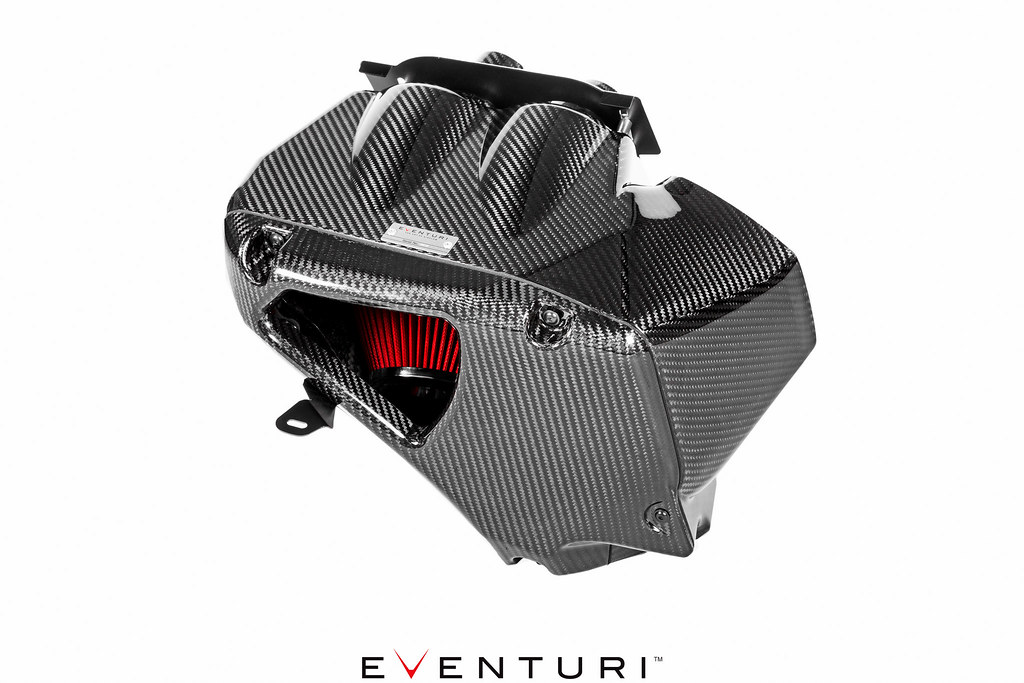 The Eventuri C7 RS6/RS7 intake system consists of a number of components engineered to perform a specific purpose and fabricated to the highest of standards. Here are the details for each component and the design ethos behind them:
Each intake system consists of:
- Carbon Fibre Airbox Enclosure
- 2 x High Flow Double Cone Air Filters
- 2 x Carbon Venturi stacks with integrated tubes
- Carbon Fibre Inlet Duct
- Carbon Fibre Front Scoop
- Laser Cut Heat Shield with Gold Reflective
- Laser Cut Stainless Steel Bracket Work
- CNC Machined Airbox Mounts
Carbon Airbox Enclosure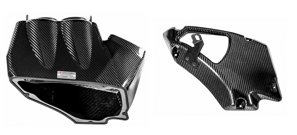
The enclosure has been designed to make the most effective use of the volume given when removing the OEM airbox. It shields the filters from the multiple sources of heat in the engine bay. The most obvious source is the engine/turbo setup itself, however there is also a heat exchanger under the headlamp which also emits significant heat. Furthermore, when the radiator fan is operating, a stream of hot air is pushed into the intake area from the radiator side just under the duct. All these heat sources require a complete airbox system as shielding - a simple cone and heat shield just cannot do the same job. During development we tested 2 open filters with heat shielding and the inlet temperatures increased significantly causing a loss of power. The airbox prevents these heat sources from adversely affecting the cone filters and is connected to the carbon duct which feeds the enclosure with cold air.
Carbon Venturi Tubes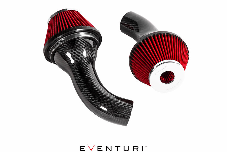
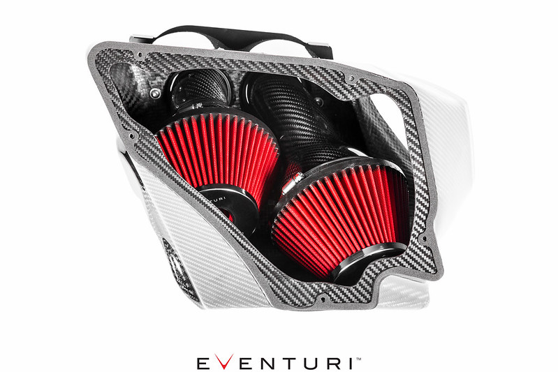
To connect our doubled coned filters to the stock turbo pipes, we designed a pair of tubes with smooth curves and with an innovative Venturi stack matched to the inner diameter of the filter neck. This curvature allows the airflow to remain laminar as it goes through the filter and enters the tubing - which is important as higher rpm where the turbos are pulling in air at high velocity. The tubing design results in an aerodynamically efficient flow path from the filters to the turbos allowing the turbos to generate boost more effectively and reducing lag. On the road this is noticeable with the car having a sharper and more eager throttle response as boost is generated quicker.
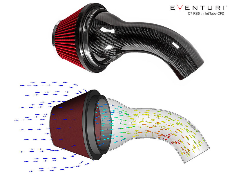 Flow Simulation
As part of our R&D process we carry out flow simulations through our intake systems to ensure that our initial concepts and calculations are reasonable. The simulation also helps us to further optimise the system for smoother airflow where possible.
The flow simulation through a single tube shows an increase in velocity from the filter to the outlet - which is expected as the cross sectional area reduces. It also shows the smooth transition between the filter and tube with the Venturi stack allowing the airflow to narrow down while remaining laminar in nature.
A complete flow simulation model of the airbox shows the saturation of flow from the 2 openings of the airbox whilst remaining steady. It also shows both tubes feeding the turbos with laminar flow as expected from the Venturi concept.
Carbon Air Duct
We redesigned the inlet duct to have a larger internal volume than the stock version. This duct feeds the airbox enclosure with ambient air from the front grill to ensure inlet temperatures are kept as low as possible.
Carbon Air Scoop
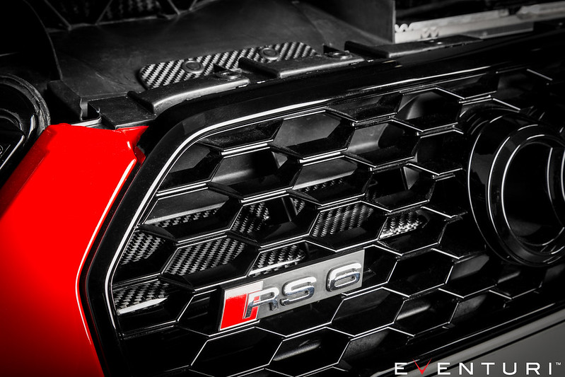
The Air scoop sits behind the front grill and forces ambient air into the duct - the curved nature of the scoop ensures that the airflow is guided as efficiently as possible while the vehicle is in motion. This allows the temperature inside the airbox enclosure to drop rapidly after the car has been at a standstill and heat soaking.
Heat Shield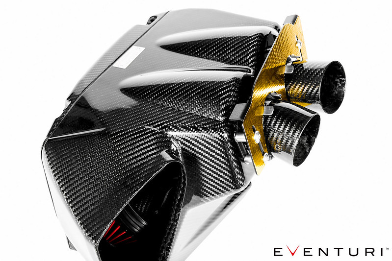
The final piece of this system is a laser cut shield with gold heat reflective to protect the face of the airbox enclosure from the direct heat of the turbos. The face of the airbox is in direct line with the top of the engine where the turbos are situated, once the engine is up to operating temperature and under load, a significant amount of heat is generated by the turbos. This heat can quickly soak the airbox so the shield ensures a thermal barrier between the turbos and airbox to maintain low inlet temperatures. A thermal imaging video was taken after several dyno runs (with the hood closed) to show the temperature difference between the hot side of the engine and the carbon enclosure: