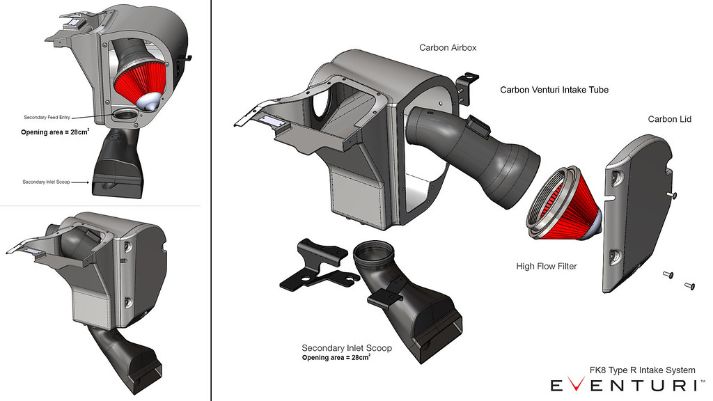
The Honda FK8 Type R intake is the result of extensive design iteration through dyno testing and flow analysis. It was developed to achieve two objectives - 1) Maintain low inlet temperatures. 2) De-restrict the turbo inlet path. The first objective was met by enclosing the filter inside a carbon airbox and using the stock seal against the hood to block out the heat soak from the engine. Since the intake sits directly behind the radiator it is crucial that the filter is not exposed which would result in a loss of power through high IAT. The second objective was met by removing the flexible tubing and optimising the inlet path with a Venturi stack connected directly to the filter. Furthermore, we added a second inlet to the airbox with a scoop pulling in air from the inner wing area. This almost doubles the total cross sectional area through which the turbo can draw from as compared with the single entry on the stock system. Our carbon airbox enclosure has been designed to maximise the use of the available volume and block all sources of heat. The resulting performance gains and aesthetics are industry leading for the FK8 Type R.
Part Numbers: - EVE-FK8-CF-INT : FK8 Civic Type R Black Carbon intake
- EVE-FK8-KV-INT : FK8 Civic Type R Kevlar intake
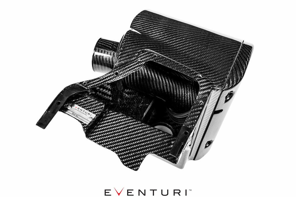 The Eventuri FK8 Type R intake system consists of a number of components engineered to perform a specific purpose and fabricated to the highest of standards. Here are the details for each component and the design ethos behind them:
Each intake system consists of:
- Prepreg Carbon Fibre Airbox Enclosure
- Custom High Flow Air Filter ISO Tested
- Carbon Venturi stack with integrated MAF tube
- Secondary Inlet Scoop
- Full Silicon Joiner with Breather Inlets
- Laser Cut Bracket Work
Carbon Airbox Enclosure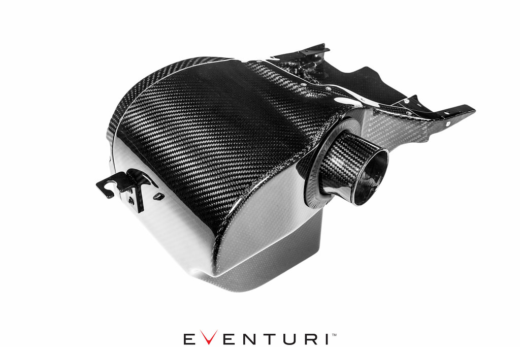
The enclosure has been designed to make the most effective use of the volume given when removing the OEM airbox. It shields the filter from the multiple sources of heat in the engine bay. The most direct source is the radiator and fan which pushes a stream of hot air directly into the intake area. The other significant heat sources are the turbo and downpipe which sit next to the intake area and once the engine is up to operating temperatures, the engine bay becomes quickly heat soaked. All these heat sources require a complete airbox system as shielding - a simple cone and heat shield just cannot do the same job. During development we tested open filters with heat shielding and the inlet temperatures increased significantly causing a loss of power. The airbox prevents these heat sources from adversely affecting the cone filter.
Carbon Venturi Tube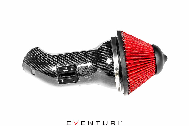
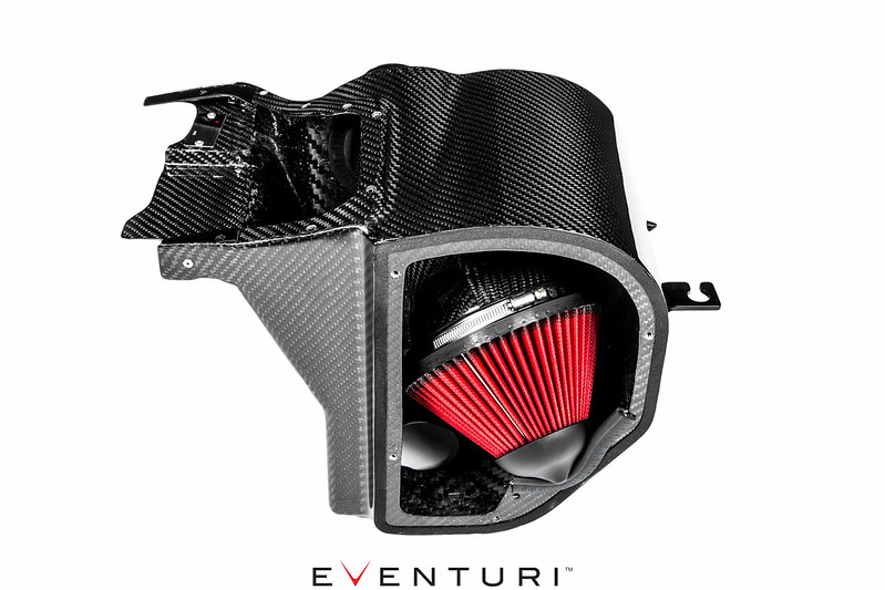
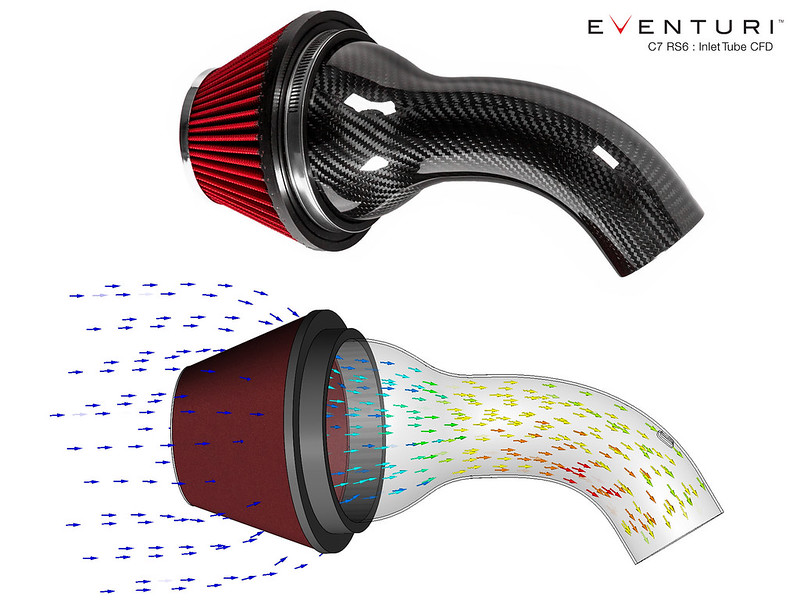
To connect our cone filter to the stock turbo pipe, we designed a tube with an integrated MAF sensor mount and an innovative Venturi stack matched to the inner diameter of the filter neck. This curvature allows the airflow to remain laminar as it goes through the filter and enters the tubing. This replaces the stock flexible rubber tube which has several deep ridges and creates turbulence in the flow path. To maintain a degree of flexibility - the tube is independent of the airbox enclosure and is able to move within the airbox, which relieves any stresses from the engine movements. The Eventuri tube design results in an aerodynamically efficient flow path from the filter to the turbo allowing the turbo to generate boost more effectively and reduce lag. On the road this is noticeable with the car having a sharper and more eager throttle response as boost is generated quicker.
 Flow Simulation
As part of our R&D process we carry out flow simulations through our intake systems to ensure that our initial concepts and calculations are reasonable. The simulation also helps us to further optimise the system for smoother airflow where possible.
The flow simulation through a single tube shows an increase in velocity from the filter to the outlet - which is expected as the cross sectional area reduces. It also shows the smooth transition between the filter and tube with the Venturi stack allowing the airflow to narrow down while remaining laminar in nature.
Secondary Inlet Scoop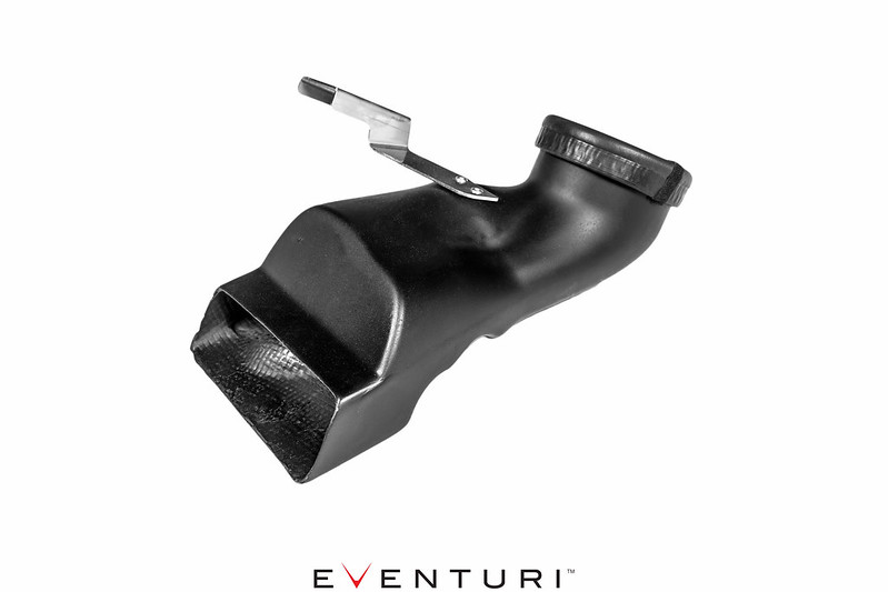
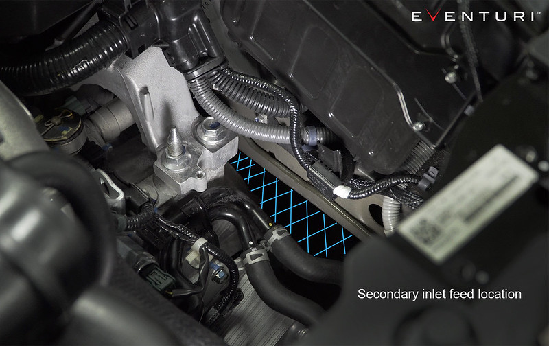
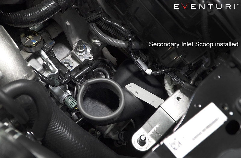
To de-restrict the turbo we had to increase the area through which it can draw air from. The stock opening behind the bumper simply was not large enough at approximately 35cm^2 so we added a second feed in the form of this scoop which seals against the base of the airbox and opens up in the inner wing area which is away from the heat sources of the engine. This adds an extra 28cm^2 cross sectional area from which the turbo can draw air from and testing showed that this was significant enough to improve the overall engine performance. The diagrams below show how the scoop and airbox come together once installed.
 Full Silicon Hose
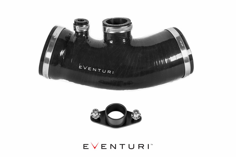
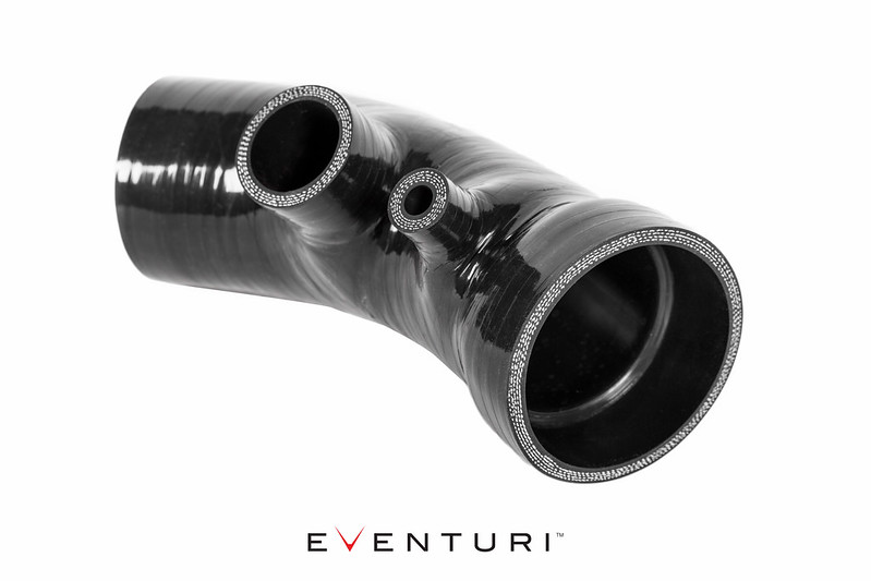
The final component is our new silicon hose which replaces the OEM hose and breather assembly all the way to the alloy turbo tube. The hose removes all the interfaces between the carbon intake and the metal turbo tube. Furthermore we have incorporated an internal step which mates to the OEM metal tube. This eliminates the exposed edge of the metal tube which is exposed with other aftermarket silicon hoses. This silicon hose is the final part of the intake and allows for smooth airflow from the intake to the turbo tube.
 Total Airflow
With all components assembled the intake is able to provide a derestricted source of airflow to the turbo with inlet temperatures kept down to a minimum. Furthermore with the airflow being smooth - the turbo is able to function more efficiently and therefore the engine produces more power.