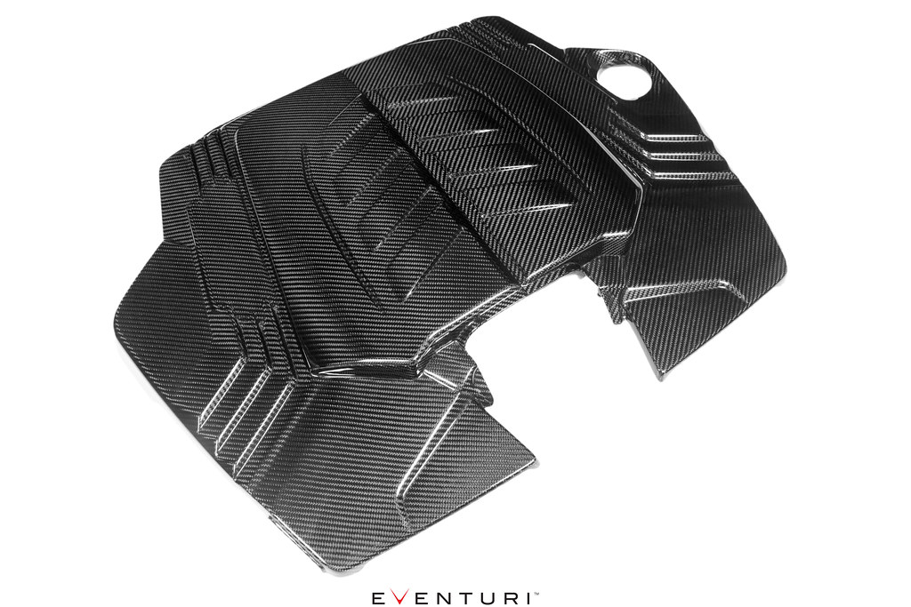
ENLARGED AIRBOX LID
The first constraint we had to overcome in order to dramatically increase the overall volume of the intake was the airbox lid. The stock lid leaves a shallow opening for the flow collector and also restricts the filtration medium being used. By creating a raised portion in the middle of the lid we are able to create more space for a larger flow collector and also for larger filters. The lid is made from prepreg carbon fibre and uses the same mounting points as the stock lid.
 CARBON FLOW COLLECTOR & FILTERS
Directing the airflow from the filters to the turbo inlets is the flow collector. The stock one is constricted in size due to eth stock kid but having removed that restriction, we were able to dramatically increase the volume of our version. In addition, this also gave us the freedom to replace the stock filter with higher flowing cone filters which also have a larger total surface area.
 TURBO INLETS
The biggest restriction in the stock system are the turbo inlets. The stock inlets not only are small in size but they also have 2 flexible sections. The flexible section immediately in front of the turbo creates turbulence as the engine moves under acceleration. To combat this, the stock inlets also have flow guides at the exit of the inlets but these also create a restriction. We removed the first flexible section which also meant that we could increase the internal volume. By increasing the inlet sizes, the turbos are able to pull in air with less restriction hence allowing for a quicker spool. In the following photos you can see the differences in the sizes.

We could have finalised the designs here however, we wanted to push the boundaries further and introduce a novel dimpled pattern to the inside surfaces. In theory, small dimples can increase the flow rate by reducing the frictional pressure losses through a tube. We have explained this in detail in our video for the G80 M3 intake which can be found
HERE.

A lot of R&D went into simulating different sizes and shapes until we settled on an optimised version which demonstrated a higher flow rate through the inlets in comparison with a smooth surface. Applying such an intricate was only possible due to the advanced manufacturing technique we employed to make the inlets, where traditional methods would not have given the accuracy required. The dimples create an "air cushion" affect over the surface of the inlet which then allows the main body of air to "slip" with less friction through the body into the turbo. This results in a more even velocity profile in a dimpled tube with the net affect being a higher velocity for the same boundary conditions. Here are the CFD simulations showing the re-circulations in the dimples and the higher velocity in the dimpled tube. Further reading can be done from these scientific papers:
Flow studies on increasing the efficiency of the inlet manifold.
Hydrodynamics of laminar flow through dimpled pipes.

The complete system comes together to provide an intake which improves on the stock airbox in performance, aesthetics and sound.........


